Thepartsguy
Well-known member
- Messages
- 1,145
- Reaction score
- 894
.
But I would only do that if your stator or AC cdi box is bad.
It’s a bit of work to convert the CDI so it’s not really a recommendation for a beginner.
BUT in the long run if you decide to go that route wait a day or two till MY DC CDI ignition shows up in the mail.. The wiring is the same for that gy6 style buggy.
Edit: day #1 score! I want a buggy like that to mess around with.
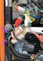
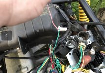
You can delete the entire ignition It uses now and build an ignition system for $35 in dc format instead of the ac system it uses now.Well, it seems this is turning out to be a lot more difficult to than I originally thought it would be. Mostly in regards to the wiring of the machine. The wiring harness was so brittle and wires kept breaking so regrettably i stripped the wiring harness. This was probably a mistake but not much to do about it at this point. Now i have been struggling to figure out the wiring diagram for my engine. I found a great video on you tube that explains the steps fairly well. However, my machine is slightly different than the video.
I have a AC cdi, 3/3 6 wire rectifier(three yellow,red,white,green) and an 11 pole stator. I have followed this diagram except changing my power input to the cdi coming from the red and black bullet connector on the stator. I have matched a place for all my wires except the white wire from regulator and the black wire from my ignition switch ( accessories wire). Also, i can not find the resistor anywhere on this engine. I don’t want to spend a fortune on fixing this engine because i ultimately want the put a more powerful engine in it. In due time of course..
But I would only do that if your stator or AC cdi box is bad.
It’s a bit of work to convert the CDI so it’s not really a recommendation for a beginner.
BUT in the long run if you decide to go that route wait a day or two till MY DC CDI ignition shows up in the mail.. The wiring is the same for that gy6 style buggy.
Edit: day #1 score! I want a buggy like that to mess around with.
Last edited: