busted_blocks
Active member
I did a bunch of research into home built dyno's. There are a lot of options and the simplest is probably something based on a motorcycle brake. For me though, I want something that can run continuously at 10kW or there abouts. I started playing with some numbers and a hydraulic based system would be complicated and pretty expensive. They can be reasonably priced if you don't want to run continuously. I also set a budget for this project of $500. Now to be fair this is a soft limit but still, if I had to spend double, I'd be pretty annoyed with myself.
Design goals:
Test engines up to 20+HP
Continuous run ability up to 10kW
Cost under $500
Simulate arbitrary engine loading patterns (simulate track conditions)
Log to a computer
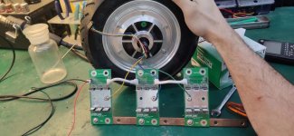
I came up with the idea to use a large permanent magnet motor as my load. By shorting the windings together, I should be able to create resistance for the motor. Using some electronics to PWM the short condition on/off I can simulate different loading. I've tried this manually and it works, but I have yet to test it with electronics. Fingers crossed this works.
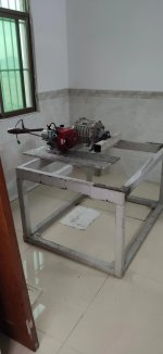
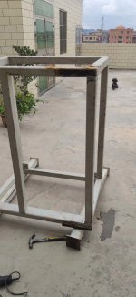
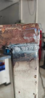
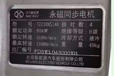
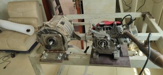
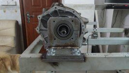
I've been sourcing scrap yard parts to keep the cost down. I found a used electric car motor. It's 80kW, water cooled and free shipping. So that's what I'm going wtih. I found a metal frame from something that had welded tabs on the bottom where I can install my isolation feet, so my neighbors downstairs don't hate me. I already have the isolation feet so I won't count those in my budget") . Metal frame is way way overkill, but cheap so what the heck. I did weld on an extra bar as originally there was some kind of roller. My welds look like the dogs breakfast, but so far I haven't had any fail.
. Metal frame is way way overkill, but cheap so what the heck. I did weld on an extra bar as originally there was some kind of roller. My welds look like the dogs breakfast, but so far I haven't had any fail.
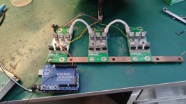
I think I have electronics around from a spot welder I built that should work. This motor is 320V so I need some high voltage MOSFets and bought a set of 600V 54A MOSfets. I'm not sure if they are used or fake, but it's worth giving them a try.
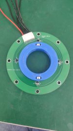
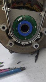
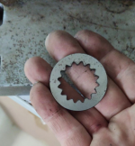
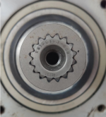
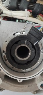
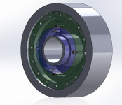
It was a bit of a challenge to find the spline that came on the motor. I haven't have to measure a spline before. After much searching I figured out it's likely ANSI B92.1, 16/32 DP, 30° 16T spline which of course isn't common. I drew one up in CAD and had it laser cut today. What do you know? fit's like a glove. Now I have the confidence in the measuring to order a sleeve.
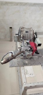
I ordered a set of gears, one for the GX200s (clutch 428 chain 13 tooth) and a matching sprocket 22 teeth for the electric motor.
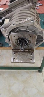
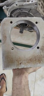
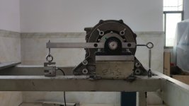
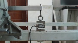
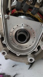
To measure the output power of the engine under test, There will be a torque arm on the electric motor connected to a load cell ($15). This will give the torque which along with the RPM can be used to find the horse power. Equations to follow later when I get around to writing the software. To do this the electric motor must be free to rotate. The front of the electric motor is 80mm so I got a suitable bearing and found a scrap motor mount that I bored out to fit the bearing. The back of the motor needed a shaft for another bearing but no need for anything big. More scrap yard junk, bearing in pillow block , aluminum bar and some machining and the electric motor is mounted.
That's about where I'm at. I didn't add up the numbers but I should still be able to afford water pump, water tank, radiator and fan.
I'm currently having trouble deciding how to best orient this massive table so when it's bolted to the floor I still have room to work and film the engine while they are running. I've attached a bunch of pics. I hope they make some sense with the story so far.
This is a learning process for me. I haven't made a dyno before and there is still plenty of places this could go horribly wrong
Design goals:
Test engines up to 20+HP
Continuous run ability up to 10kW
Cost under $500
Simulate arbitrary engine loading patterns (simulate track conditions)
Log to a computer
I came up with the idea to use a large permanent magnet motor as my load. By shorting the windings together, I should be able to create resistance for the motor. Using some electronics to PWM the short condition on/off I can simulate different loading. I've tried this manually and it works, but I have yet to test it with electronics. Fingers crossed this works.
I've been sourcing scrap yard parts to keep the cost down. I found a used electric car motor. It's 80kW, water cooled and free shipping. So that's what I'm going wtih. I found a metal frame from something that had welded tabs on the bottom where I can install my isolation feet, so my neighbors downstairs don't hate me. I already have the isolation feet so I won't count those in my budget
. Metal frame is way way overkill, but cheap so what the heck. I did weld on an extra bar as originally there was some kind of roller. My welds look like the dogs breakfast, but so far I haven't had any fail.I think I have electronics around from a spot welder I built that should work. This motor is 320V so I need some high voltage MOSFets and bought a set of 600V 54A MOSfets. I'm not sure if they are used or fake, but it's worth giving them a try.
It was a bit of a challenge to find the spline that came on the motor. I haven't have to measure a spline before. After much searching I figured out it's likely ANSI B92.1, 16/32 DP, 30° 16T spline which of course isn't common. I drew one up in CAD and had it laser cut today. What do you know? fit's like a glove. Now I have the confidence in the measuring to order a sleeve.
I ordered a set of gears, one for the GX200s (clutch 428 chain 13 tooth) and a matching sprocket 22 teeth for the electric motor.
To measure the output power of the engine under test, There will be a torque arm on the electric motor connected to a load cell ($15). This will give the torque which along with the RPM can be used to find the horse power. Equations to follow later when I get around to writing the software. To do this the electric motor must be free to rotate. The front of the electric motor is 80mm so I got a suitable bearing and found a scrap motor mount that I bored out to fit the bearing. The back of the motor needed a shaft for another bearing but no need for anything big. More scrap yard junk, bearing in pillow block , aluminum bar and some machining and the electric motor is mounted.
That's about where I'm at. I didn't add up the numbers but I should still be able to afford water pump, water tank, radiator and fan.
I'm currently having trouble deciding how to best orient this massive table so when it's bolted to the floor I still have room to work and film the engine while they are running. I've attached a bunch of pics. I hope they make some sense with the story so far.
This is a learning process for me. I haven't made a dyno before and there is still plenty of places this could go horribly wrong
Attachments
-
 test setup2.jpg2.2 MB · Views: 9
 -
 test setup1.jpg1.9 MB · Views: 9
 -
 bearing mount test.jpg2.4 MB · Views: 8
 -
 bearing mount.jpg2 MB · Views: 8
 -
 frame1.jpg1.9 MB · Views: 8
 -
 weld.jpg2.4 MB · Views: 8
 -
 spline test2.png683.2 KB · Views: 7
 -
 spline test.png489.4 KB · Views: 6
 -
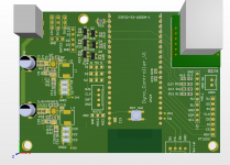
 motor spec.png940.9 KB · Views: 8


 .
.