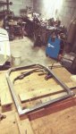
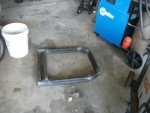
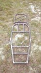
We welded up the rear frames tonight. It took a little longer than it should have because we had to build a flat table top to weld on and make a jig on.
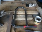
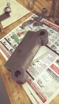
The two cross bars that hole the motor mount plate were about 1/8" to long and would have had to have been forced in so I will trim them in the mill tomorrow before welding in.
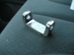
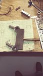
We did some destructive testing by welding some scraps of the same material that we are using then beating it with a hammer until it failed. The metal around the weld tore and left the weld in place. I have 100% confidence in the strength of the welds, even if they are not the prettiest.
The two cross bars that hole the motor mount plate were about 1/8" to long and would have had to have been forced in so I will trim them in the mill tomorrow before welding in.
We did some destructive testing by welding some scraps of the same material that we are using then beating it with a hammer until it failed. The metal around the weld tore and left the weld in place. I have 100% confidence in the strength of the welds, even if they are not the prettiest.
Attachments
-
 my rear frame.jpg128 KB · Views: 17
") If you have more pics and some time!
If you have more pics and some time!